Disclaimer:
While I worked for VMware from March 2019 and up until the Broadcom acquisition in November 2023, and continued on with Broadcom, this post (and website as a whole) is solely for my purposes and in no way represents VMware or Broadcom’s views or best practices. Heck, for all I know, this is accidentally working in my lab. Either way, VMware nor Broadcom are officially backing this post.
Introduction
It’s odd to me that I have been a part of the virtual world for quite a while now and have just finally come to terms that I really should figure out the basics of VMware NSX. With Broadcom’s shift to pushing VMware VCF, this just makes sense. However, even with a Cisco CCNA certification under my belt for the last seven years and working with networking equipment for the past ten years, VMware NSX continues to confuse me and only recently am I starting to make sense of it.
Hopefully this post will help others out there that are trying to learn VMware NSX and the nuances that go long with it, especially in a nested lab.
Let’s Get Physical
Even the best virtual labs in the world require physical infrastructure. My humble lab consists of the following physical equipment, accurate as of 1/23/2024:
- One (1) Firewalla Gold, running 1.9770 (Box Version) and 1.56.1 (App Version)
- One (1) J4903A HP ProCurve Switch 2824, running I.10.107
- One (1) Dell PowerEdge R730xd (the Host), running up-to-date firmware
- Operating System: VMware ESXi 7.0 Update 3o | 28 SEP 2023 | Build 22348816
- vCenter (managing the nesting host): VMware vCenter Server 7.0 Update 3p | 07 DEC 2023 | ISO Build 22837322
- Processor: Intel(R) Xeon(R) CPU E5-2640 v3 @ 2.60GHz (Haswell)
- Sockets: 2
- Cores per Socket: 8
- Logical Processors: 32
- Hyperthreading: Active
- Memory: 256 GB
- Storage:
- Local Datastore: 1.36 TB (Five (5) x 278.88 GB physical disks)

Where’s the Logic in That
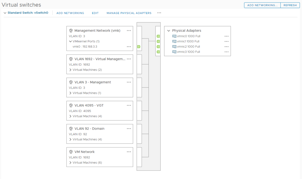
Here is the networking set up for the nesting host. A few key elements must be set for the nested guests to work correctly.
- Virtual Standard Switch (VSS): vSwitch0
- Physical Adapters: Four (4) x 1 Gbit/s
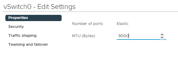
On the vSwitch, I raised the Maximum Transmission Unit (MTU) to 9000 Bytes to match the physical switch. (This configuration is also known as setting Jumbo Frames, although technically, a jumbo frame is any setting greater than 1500 Bytes.)
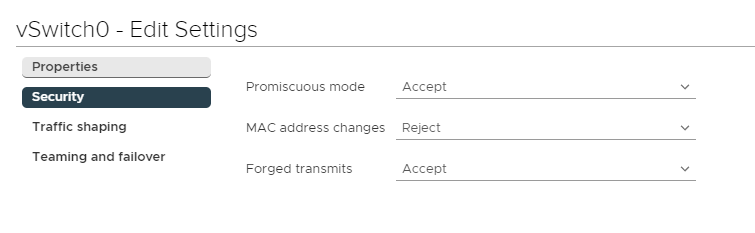
Also on the vSwitch, the Security policy must be configured with Promiscuous mode and Forged transmits to Accept. Promiscuous mode allows the vSwitch to see all network traffic traversing the virtual switch. Forged transmits allows the traffic to traverse the switch without being dropped due to not matching the MAC address for the virtual machine.
The guests and their VLAN ID that make up the nested lab are:
- VLAN 92 – aaronrombaut.com Domain Resources
- dc-10, Windows Server 2022, the domain controller for aaronrombaut.com, providing Domain Name System (DNS) services
- fileserver, Fedora Linux 39 (Server Edition), the file server and NTP server for aaronrombaut.com
- pfSense, pfSense Community Edition 2.7.2-RELEASE (FreeBSD), this is the simulated WAN interface for the nested lab infrastructure
- VLAN 1692 – Nested Virtual Management
- vcsa-100, VMware vCenter Server 7.0 Update 3p | 07 DEC 2023 | ISO Build 22837322
- nsxmgr-201, VMware NSX 4.1.2.1 | 07 NOV 2023 | Build 22667789
- Note: The guests above manage the nested virtual infrastructure, but are better situated on the physical host rather than nested in due to resources. This also somewhat simulates them being in a management cluster.
- VLAN 4095 – Virtual Guest Tagging (VGT) (virtual machines handle VLAN traffic)
- pfSense, pfSense Community Edition 2.7.2-RELEASE (FreeBSD), this is the LAN interface for the nested lab infrastructure
- esxi-101, VMware ESXi 7.0 Update 3o | 28 SEP 2023 | Build 22348816
- esxi-102, VMware ESXi 7.0 Update 3o | 28 SEP 2023 | Build 22348816
- esxi-103, VMware ESXi 7.0 Update 3o | 28 SEP 2023 | Build 22348816
The Nitty Gritty
I would first like to provide a quick tour of the nested virtual infrastructure. One thing to note here is that I am only running one (1) NSX Manager Node. In production, I would run three (3) as a best practice, but not having three in the lab does not affect the configuration.
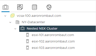
The Nested Datacenter and Cluster
Here we can see that this is a simple three node cluster.
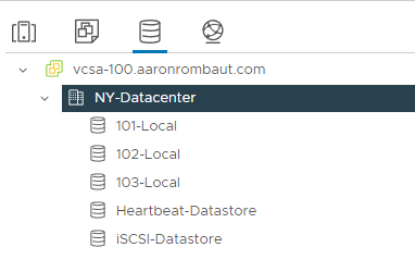
The Datastores
Each nested host has a local datastore and there are two shared iSCSI datastores present. One is for virtual machines (guests) and I added a second datastore just for heartbeat monitoring, called Heartbeat-Datastore. None of this will affect NSX, just part of the tour.
The Nested Virtual Networking
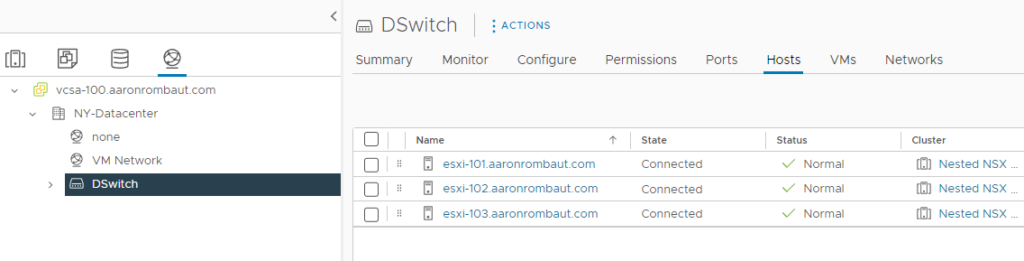
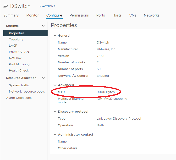
I have a Distributed Virtual Switch (DVS) configured and all three nested hosts attached.
Maximum Transmission Unit (MTU) adjusted to 9000 Bytes.
I have NSX already set up, so that’s why the segments show up, but for now, let’s focus on the VLANs. This was really tricky for me to figure out for some reason. The tricky part was figuring out how the NSX Uplink Profiles worked. I will explain more when reviewing the profiles.
When a port group is configured with a defined VLAN ID, it acts like an access port in Cisco, or an untagged port in HP. Basically, there is no 802.1q tagging taking place. Whatever is attached to the port group will be in that defined VLAN.
When a port group is configured with VLAN trunking, it acts like a trunk port in Cisco, or a tagged port in HP. Basically, 802.1q tagging is required. Whatever is attached to the port group will not be on any network without configuring a VLAN ID (providing an 802.1q tag) in the guest.
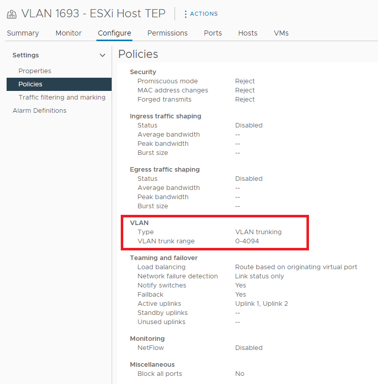
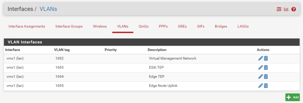
Here is an explanation of the VLANs I have configured and their respective VLAN type.
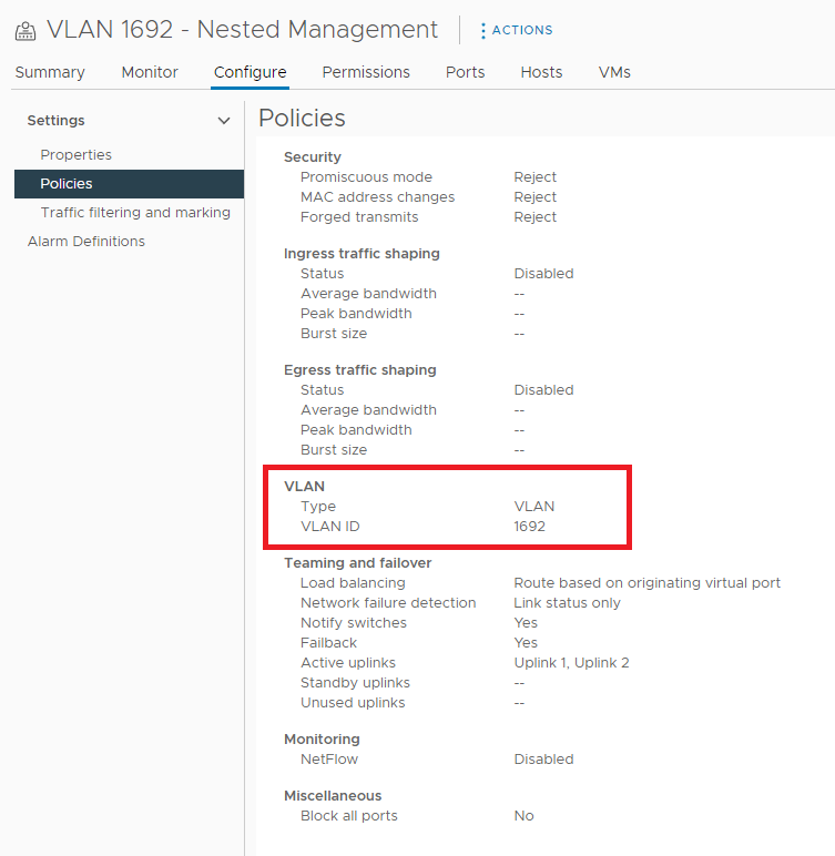
- VLAN 1692 (VLAN 1692): Nested Virtual Management
- VLAN 1693 (VLAN trunking): ESXi Host TEP
- VLAN 1694 (VLAN trunking): Edge Node TEP
- VLAN 1695 (VLAN trunking): Edge Node Uplinks
Note that I originally did try to place the Edge Node TEPs on the same VLAN as the ESXi Host TEPs (why not, right? why add a whole other subnet if it is a tunnel endpoint), but later realized that this was not supported (or is supported, but only in certain scenarios as outlined in the following knowledge base, NSX-T Edge TEP networking options (83743).
In the end, I decided to add ESXi Host TEPS to one VLAN and Edge Node TEPS to another VLAN. This kept the VMware NSX infrastructure “outside” of NSX, as-in, not needing to add segments, in order to prepare the infrastructure for NSX.
These VLANs are built out on the pfSense virtual appliance. I had to use a nested pfSense appliance since my hardware firewall, the Firewalla Gold, does not have out-of-the box features, such as being able to adjust the Maximum Transmission Unit (MTU) or support for Border Gateway Protocol (BGP).
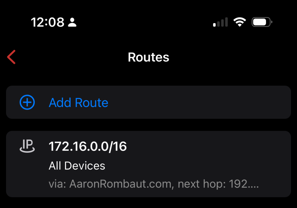
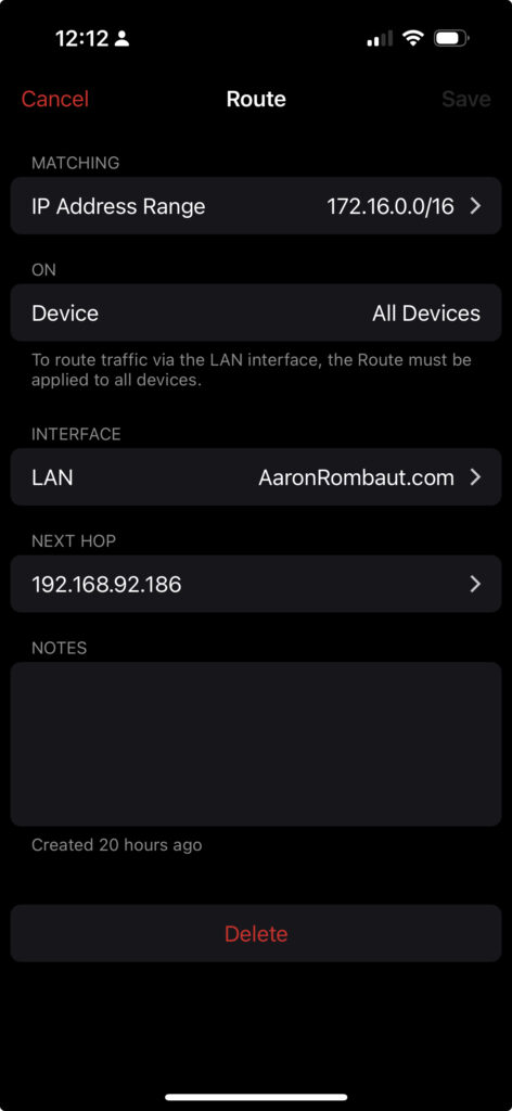
Since the VLANs that matter are in the 172.16.0.0/16 range, I added a static route from my Firewalla Gold router to the nested pfSense appliance.
Then, from my computer, I tested connectivity with ICMP (ping.exe) to each of the gateway interfaces on the pfSense, ensuring that any firewall rules on the pfSense were configured to allow the traffic.
The Nested pfSense Appliance
I actually started out with static routes, just until I was able to get point-to-point traffic to pass. As soon as I had it worked out, I configured Border Gateway Protocol (BGP) on the pfSense and rolled that. The BGP configuration is discussed later in this post. If you prefer Open Shortest Path First (OSFP), that can also be configured. The main thing to take away here how the physical host is configured and how the pfSense networks are configured over the top.
Speaking of pfSense, I should probably back up a bit and provide details on how I have this nested virtual appliance configured.
First things, first, I used the pfSense firewall since my hardware (the Firewalla Gold) has limitations (as mentioned above). I am also more familiar with pfSense over other open source firewalls. So, I installed pfSense on the physical host and provided it two network adapters, one for a simulated WAN and the other to serve the nested virtual machines in the LAN. (Make sure to install the Open-VM-Tools package)
Here is what the pfSense looks like in relation to the physical network and host.

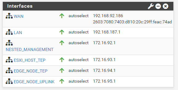
pfSense Interfaces
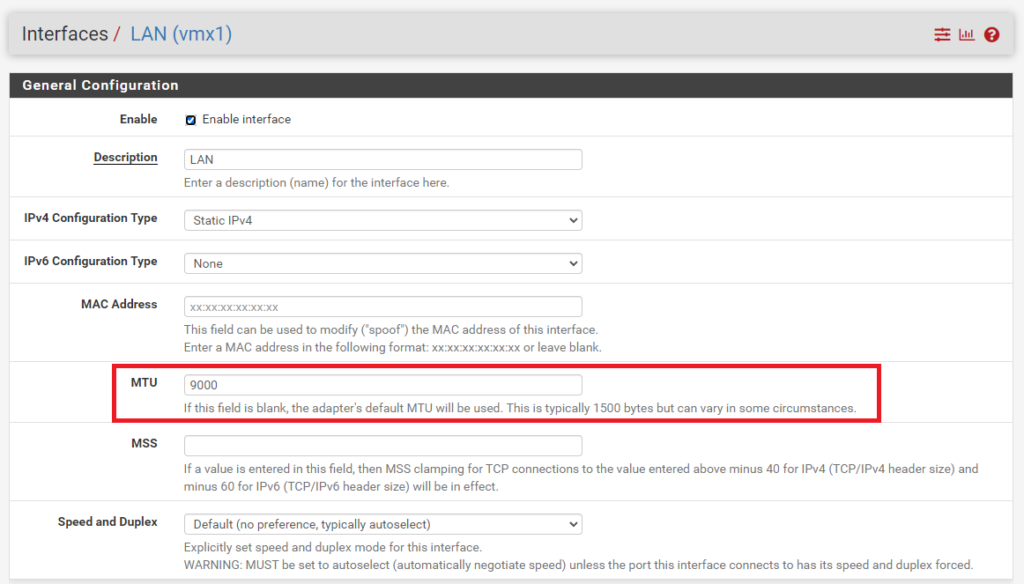
Before configuring sub-interfaces, I needed to configure the LAN interface with an MTU of 9000 since the TEP sub-interfaces would need to be configured with this. The LAN interface in this case is not used for anything besides a parent interface for the sub-interfaces.
In pfSense, I configured all the VLANs I would need and attached them to the LAN parent interface.
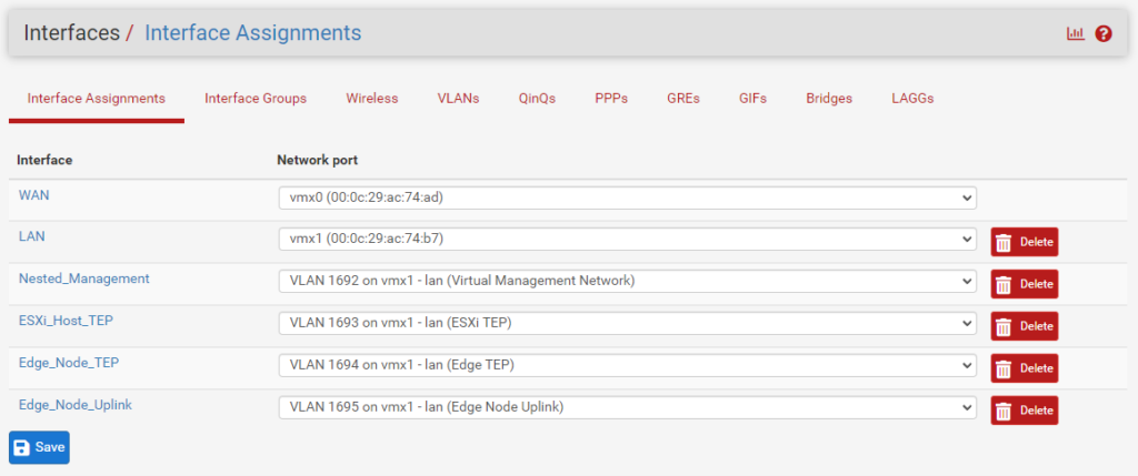
Next, I configured the Interface Assignments. The rules for my networks are as follows:
- The VLAN ID is the middle of the IPv4 address
- IPv4 is configured with a Static IPv4 address
- IPv6 is not configured, setting is None
- The .1 is the gateway interface on the pfSense appliance
- All networks are /24, regardless of usage
- LAN interfaces do not Block private networks and loopback addresses or Block bogon networks
The following is a breakdown of the assignments with the MTU.
- VLAN 1692 has an address of 172.16.92.1/24, MTU is default (1500)
- VLAN 1693 has an address of 172.16.93.1/24, MTU is 9000
- VLAN 1694 has an address of 172.16.94.1/24, MTU is 9000
- VLAN 1695 has an address of 172.16.95.1/24, MTU is default (1500)
pfSense – FRR – Border Gateway Protocol (BGP)
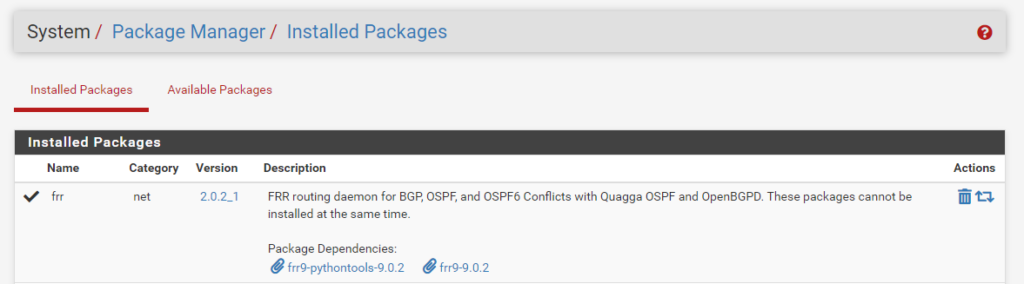
I mentioned at the beginning of this section that I configured BGP after I had traffic pass end-to-end. To get started with BGP on the pfSense appliance, I installed the frr package (Free Range Routing) on pfSense. I then followed the BGP Example Configuration on Netgate Docs.
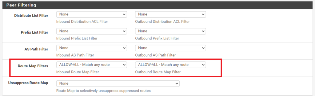
Configuring the Route Maps.
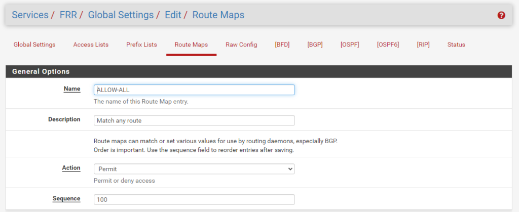
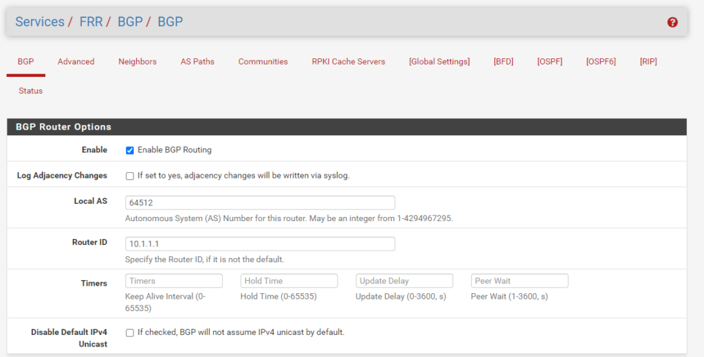
Enabling and Configuring BGP
For my lab, I decided to use the first private Autonomous System (AS) number, 64512, for the pfSense BGP Router. The range of private AS numbers is 64512 through 65534, according to iana.org.
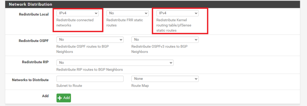
Configuring BGP Network Distribution
There was one very important modification I had to make from the example configuration. I did not realize it until I was troubleshooting much later on. The example only provides a single network to distribute. I wanted to Redistribute connected networks (all IPv4 networks), and later on, discovered I also wanted to Redistribute Kernel routing table/pfSense static routes.
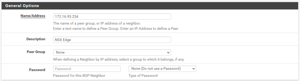
Configuring BGP Neighbors
This may be set up now, since we have a network plan, but if this is just getting set up, it can be configured later. For completeness sake, I am going to include here.
As for the NSX edge, I am going to just use the next private AS number, 64513, and the opposite end of the IPv4 /24 address space, so the .254.

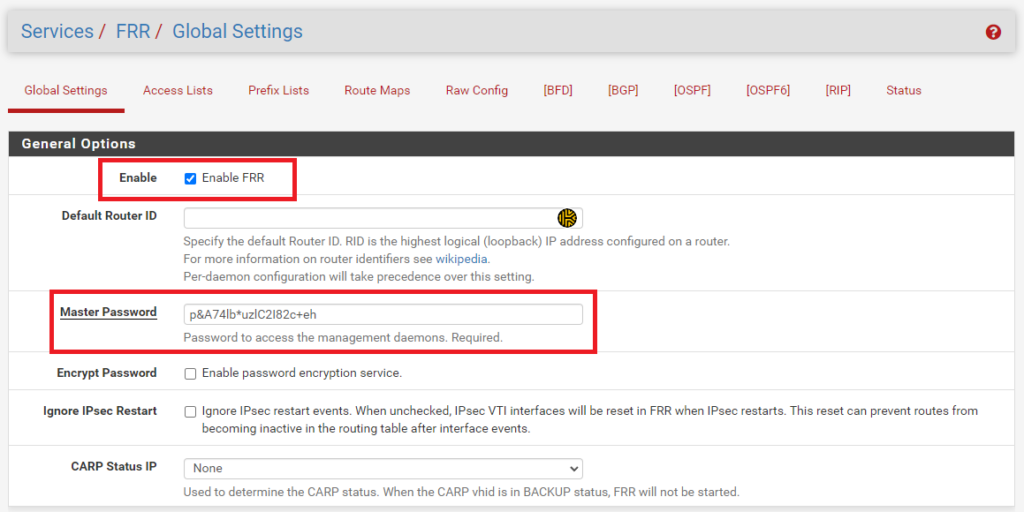
Finally, all that is left to do is to enable FRR, globally.
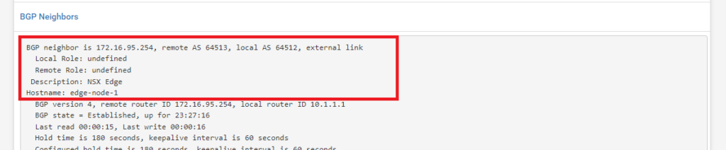
Confirming BGP Neighbors
pfSense – Firewall Rules
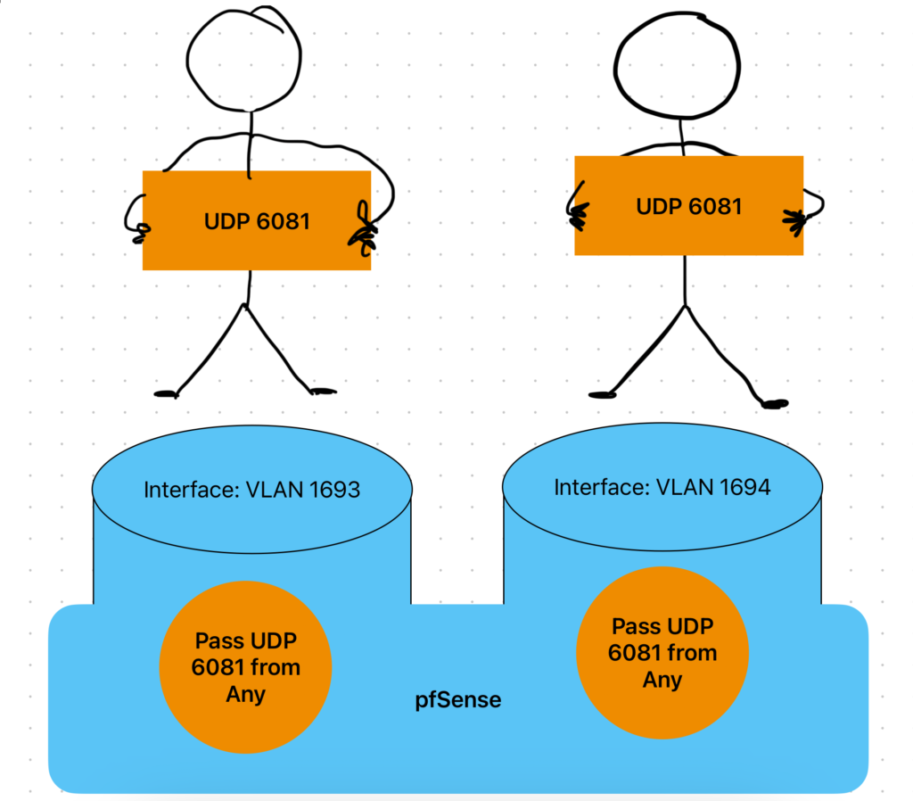
Ah pfSense and your rules. One thing I learned a long time ago when configuring pfSense Firewall rules, it helps to imagine standing on top of the interface I am interested in. For example, trying to pass the Geneve tunneling protocol, UDP port 6081. I know I will be passing traffic from VLAN 1693 – ESXi Host TEPs to VLAN 1694 – Edge Node TEPs. Therefore, I imagine I am standing on top of the VLAN 1694 – Edge Node TEPs interface and want to drop in an Ethernet Frame. I need to provide a Pass action for this to happen. The same goes for the opposite interface. These two interfaces must be permitted to pass Geneve tunneling protocol traffic back and forth. The rule I established is wide open (from Any) and could be further restricted, but for my lab I am OK with this. The root of this lab was to get nested NSX up and running, not study for an advanced Cyber Security Networking certification.
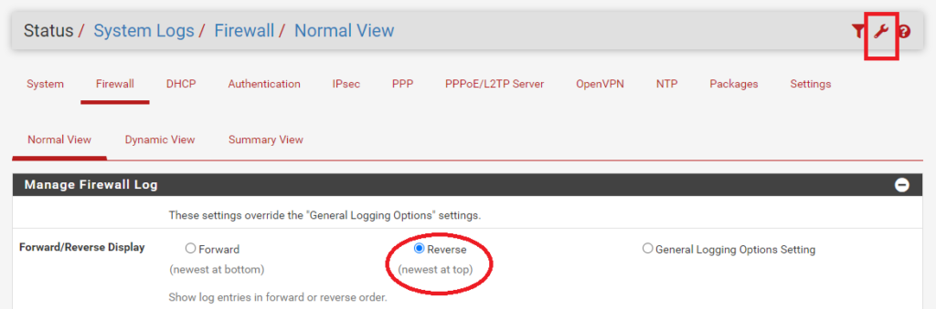
The most valuable tool in this section for me is the Firewall logs. These can be found at Status > System Logs > Firewall. I always adjust Firewall Log settings to show in Reverse, where the newest logs are at the top.
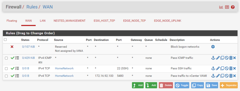
WAN Rules
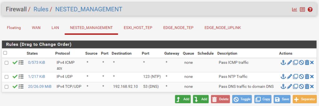
VLAN 1692 – Nested Virtual Management
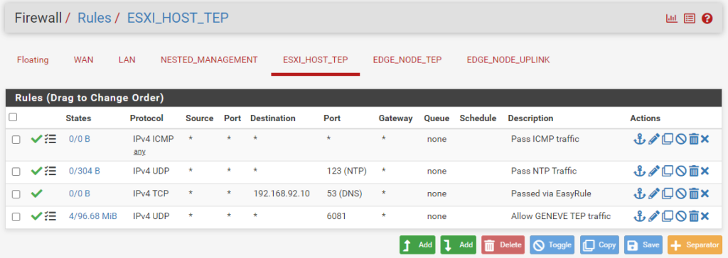
VLAN 1693 – ESXi Host TEPs
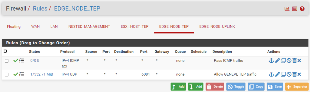
Important: UDP Port 6081 must be open to allow the Geneve tunneling protocol to pass.
VLAN 1694 – Edge Node TEPs
Important: UDP Port 6081 must be open to allow the Geneve tunneling protocol to pass.
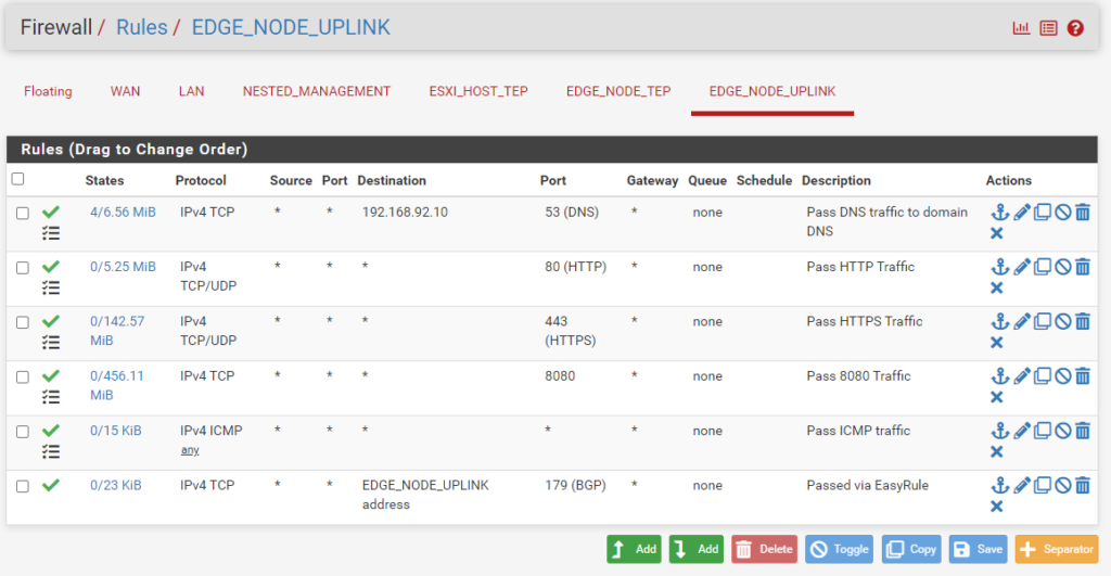
VLAN 1695 – Edge Node Uplink
Important: TCP Port 179 must be open to allow BGP traffic to pass.
VMware NSX
Licensing
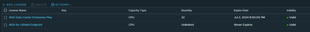
System > Settings > Licenses
The very first thing to do after deploying the first NSX Manager and logging in is to configure the license.
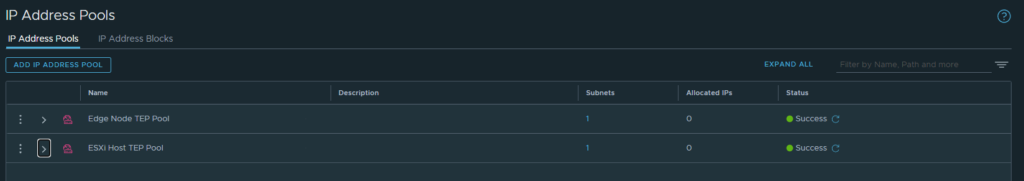
IP Pools
Networking > IP Management > IP Address Pools > IP Address Pools
ESXi Host TEPs can be configured with DHCP or IP Pools. I did play around with using both, but decided that since the Edge Nodes could not use DHCP (why is that?) that it would likely be better for uniformity to just use IP Pools for each. I created two separate IP Pools, one for ESXi Host TEPs and another for Edge Node TEPs.
Prepare the NSX Infrastructure
At this point, we are going to prepare the infrastructure for NSX. We will start at the bottom of the Fabric menu and work our way up.
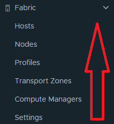
Settings
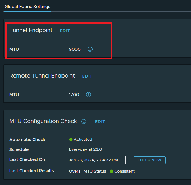
System > Configuration > Fabric > Global Fabric Settings
I decided to change the Tunnel Endpoint MTU to 9000 to match the virtual distributed switch MTU.
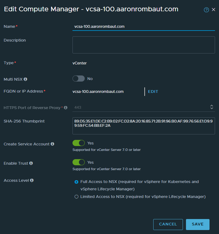
Compute Managers
System > Configuration > Fabric > Compute Managers
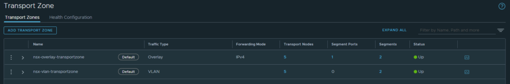
Transport Zones
System > Configuration > Fabric > Transport Zones > Transport Zones
I decided to use the default Transport Zones.
Profiles
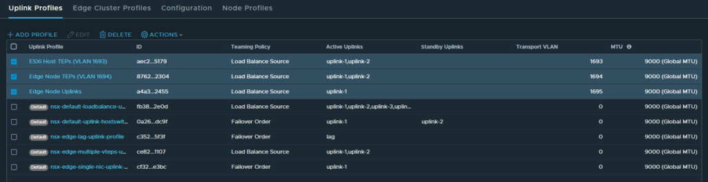
System > Configuration > Fabric > Profile > Uplink Profiles
This was one of the stickiest configuration items for me to grasp. More specifically, the Transport VLAN in the Uplink Profile. Do I set it? Do I not set it? Do I not set it here and add it in the Transport Zone? Needless to say, but I spent way too many hours figuring this out and how it related to the Port Groups configured on the virtual distributed switch (vds). If you are following along from the beginning of this post, you will see that I finally ended up configuring the Port Groups with VLAN trunking as the VLAN type. I found this to be the easiest configuration, overall. Set the Port Group to VLAN trunking (outside of NSX) and configure the needed VLANs from within NSX Manager.
The other part, I later found out, was that ESXi Hosts and Edge Nodes are not able to share the VLAN except in certain configurations (as described earlier). In the end, I configured three separate Uplink Profiles. They are pretty straight forward at this point. Name the profile, set a Teaming Policy (which I used Load Balance Source), set the Active Uplinks (why would I want to use Standby Links? Goodbye $$$ and bandwidth), and finally, configure the appropriate VLAN. Do not set an MTU here!
Here is the note for MTU in the Edit Uplink Profile window:
Note: For ESXi hosts, MTU value is not applicable. You can leave the MTU field empty for ESXi hosts. For Edge nodes and physical servers, if you do not enter any value in the MTU field, NSX takes the default MTU value of 9000.
Nodes
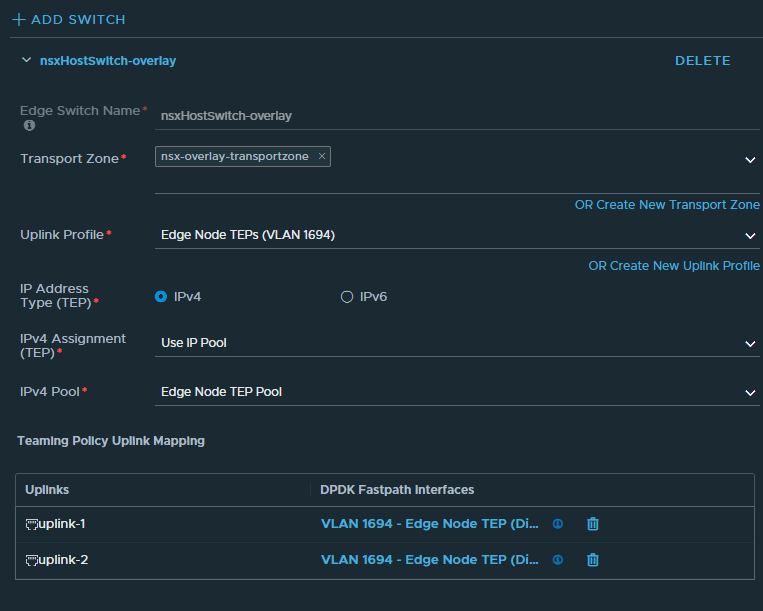
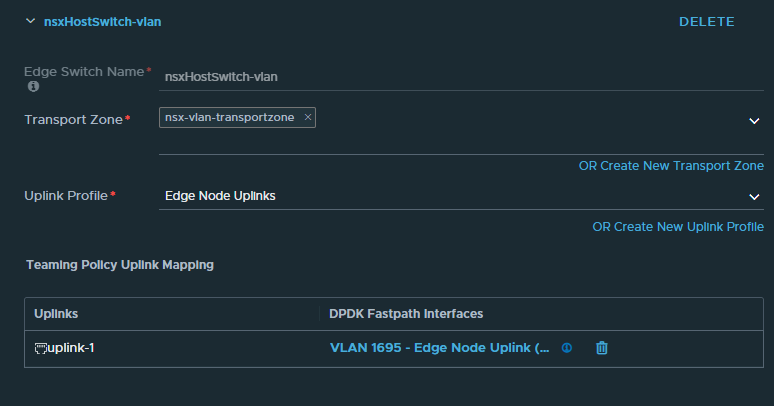
System > Configuration > Fabric > Nodes > Edge Transport Nodes
Ok, this was another sticky point in my learning. I tried and tried to set up a single switch with both transport zones configured and just could not ever figure out how to map the interfaces on the N-VDS to the nested host interfaces. In the end, I decided to build two separate N-DVS, one for Overlay and the other for VLAN traffic.
The Overlay switch…
The VLAN (Uplinks) switch…
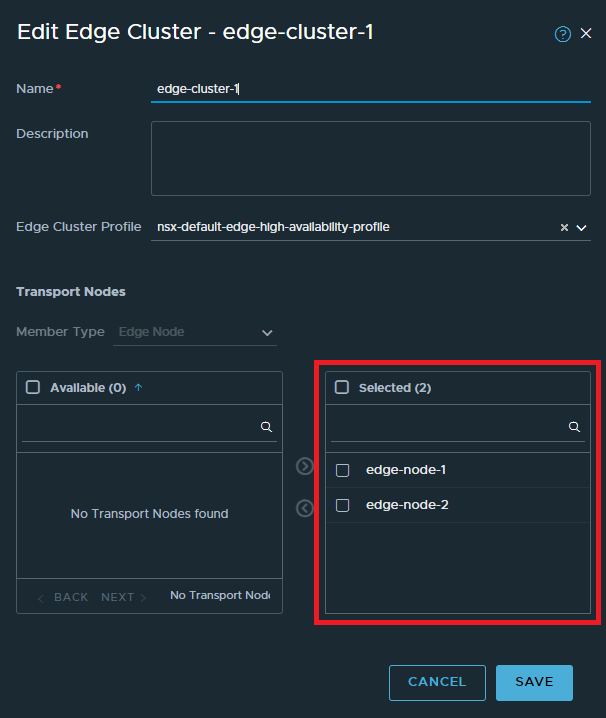
System > Configuration > Fabric > Nodes > Edge Clusters
The Edge Cluster concept was fairly easy to grasp. Build a container and populate it with Edge Transport Nodes.
Hosts
System > Configuration > Fabric > Hosts > Transport Node Profile
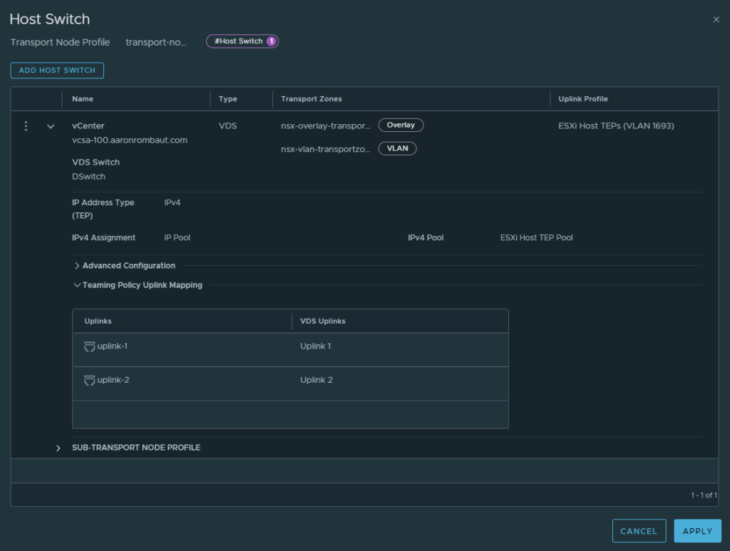
I decided to add my three ESXi Hosts in both Transport Zones. This Profile was not too bad to figure out once I got past figuring out how the Uplink Profiles worked. I did play around with using DHCP and just using IP Pools, too. I found that I could use an Uplink Profile with two VDS Uplinks, successfully, so I made sure the ESXi Host TEPs Uplink Profile was configured for two uplinks.
Configure NSX
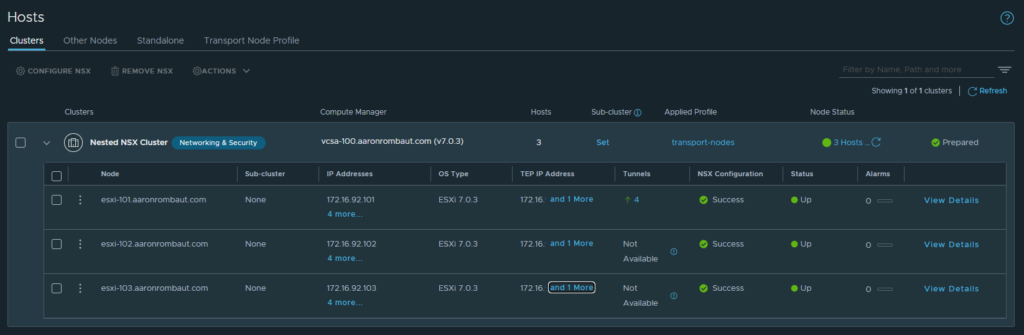
System > Configuration > Fabric > Hosts > Clusters
Once the Transport Node Profile was configured, this was super simple to configure. Select the cluster checkbox, click Configure NSX, and choose the Transport Node Profile.
At this point, the infrastructure should be configured for NSX. Next, we can configure our actual segments and gateways.
Segments and Gateways
At this point, if you have been following along, the infrastructure is prepped and now we can start building the Layer-2 (Segments) and Layer-3 (Gateways).
Segments are like VLANs but VLANs are limited to only 4,094 due to there being a finite 12-bit VLAN identifier (VID) field in the Ethernet Frame. Since Segments are encapsulated in the Geneve tunneling protocol, they are given 24-bits of space which can provide 16,777,215 Virtual Network Identifiers (VNI)! VMware limits static or dynamic port groups per vCenter to 10,000, however.
Tier-1 Gateways provide East-West traffic flow. They connect Segments and allow traffic to pass. In a multi-tenant environment, these would likely be controlled by the tenant.
Tier-0 Gateways provide North-South traffic flow. This is how ethernet traffic ingresses and egresses the virtual infrastructure. In a multi-tenant environment, these would likely be controlled by the service provide. This is where the various static and dynamic routing (BGP or OSPF) protocols are configured.
Gateway Configuration Tasks
VMware education suggests the following order when configuring the gateways.
- Create the Tier-1 Gateway and it’s segments
- Connect the segments to the Tier-1 Gateway
- Create uplink segments
- Create the Tier-0 Gateway and define the uplink connections
- Configure static or dynamic routing on the Tier-0 gateway
- Configure the connectivity between the Tier-0 and the Tier-1 gateways
- Enable route advertisement and redistribution
Segments
Networking > Connectivity > Segments
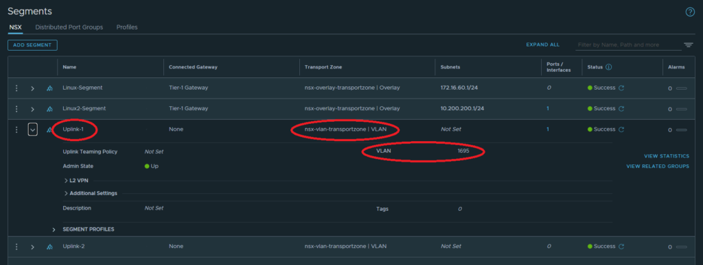
Creating an uplink segment for the Tier-0 Gateway. This will be a VLAN Segment.
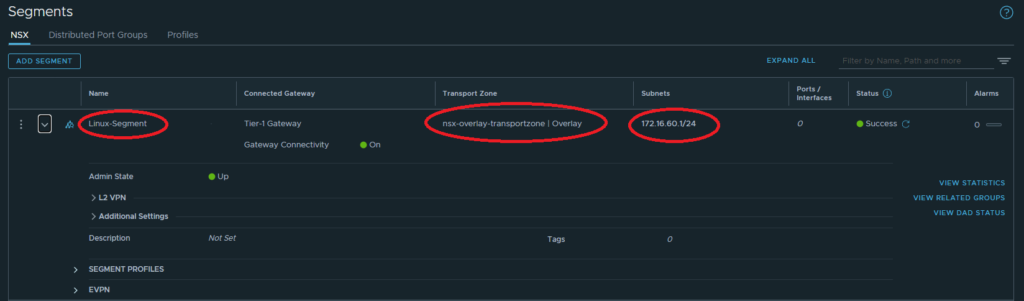
Other Segments can be created now or later. I will configure one additional Segment, now, called Linux-Segment. This will be an Overlay Segment. The image below shows a Connected Gateway. Depending on when the Segment is created, Gateways may or may not be created and available. This can be configured later, either way.
Tier-1 Gateways
Networking > Connectivity > Tier-1 Gateways
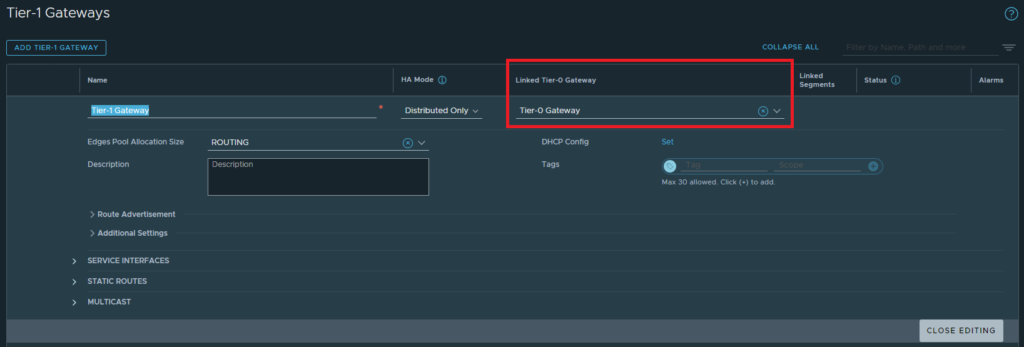
Pay attention to the HA Mode when creating the Tier-1 Gateway, it is Active Standby by default. Most likely, Distributed Only will need to be configured. When I was first learning this, I just built a default Tier-1 Gateway and then only through formal training did I pick up on that configuration item and re-configure. Things worked a lot better after.
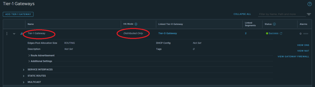
In the image above, the Tier-1 Gateway is linked to a Tier-0 Gateway. This can be configured after the Tier-0 gateway is configured. You may also notice that there are Linked Segments. This number will increment as Segments are connected.
Tier-0 Gateways
Networking > Connectivity > Tier-0 Gateways
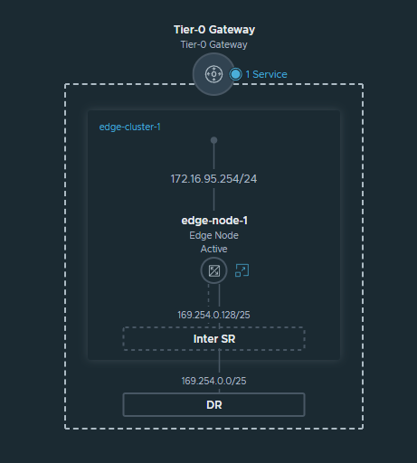
Ah…this was the worst, most frustrating component for me to grasp, paired with the related Edge Nodes and connectivity.
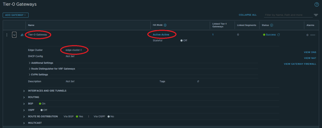
First off, create the Tier-0 Gateway, leaving HA Mode as Active Active and choosing the appropriate Edge Cluster. After the initial Save, then click Yes to continue configuring the Interfaces and Routing.
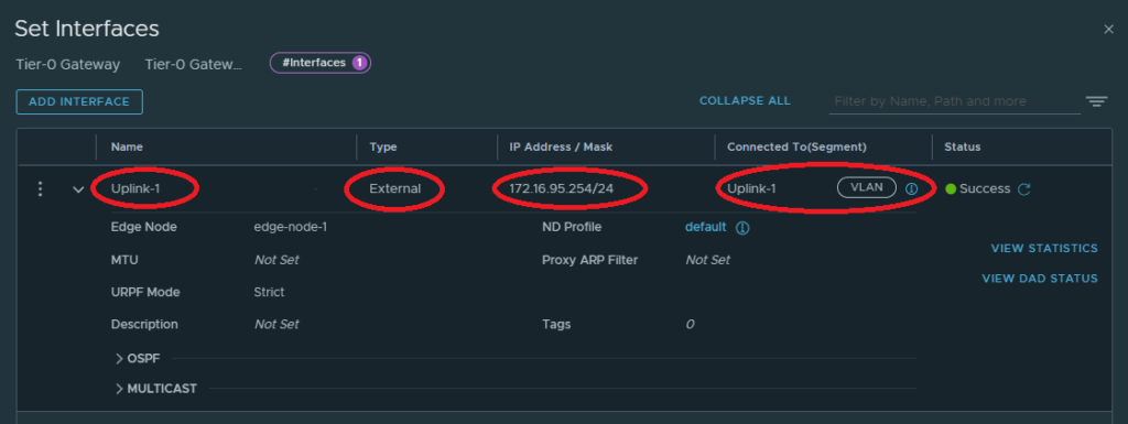
Tier-0 Gateway Uplink Interface
Configuring the uplink interface involves providing a Name and IP address. This IP address should be on the subnet that belongs to the uplink Segment. In my lab, the Uplink Network is presented by the nested pfSense appliance. The VLAN is 1695 and therefore the subnet is 172.16.95.0/24. Since my network rules (personal preference, not an actual configured rule/policy) on pfSense required me to use the .1 address, I decided to use the opposite end of the /24 and use 172.16.95.254/24 as the uplink interface for this router. This address gets assigned to the service router component of the Edge Node. Later when traffic egresses NSX, it will egress the .254 and ingress the .1 on pfSense when heading northbound.
Tier-0 Gateway Routing
There are two paths here, static or dynamic. When starting out, I just used a static route so that I could prove out the network traffic passing from my physical network in and out of the virtualized network.
Later, I configured Border Gateway Protocol (BGP) on the nested pfSense appliance. Since this was the first time configuring BGP on pfSense, I also had to learn and troubleshoot that side.
Tier-0 Gateway Routing – Static
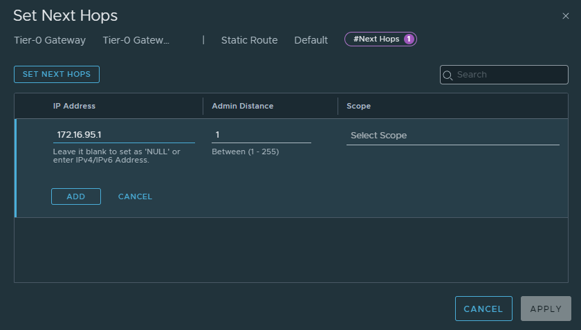
To configure static routing, edit the Tier-0 Gateway and Set the Static Routes under the Routing heading. I called my static route, Default, and provided a 0.0.0.0/0 Network which encompasses all traffic not known within NSX.
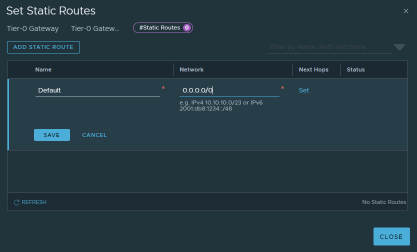
Next, Set a Next Hop. In my lab, like described above when configuring the Interfaces, I need to egress my traffic to the pfSense router, i.e. 172.16.95.1. I did not need to configure a Scope, so I left it blank here. If there are multiple Interfaces, i.e. paths, I think that is when a scope can be set.
Tier-0 Gateway Routing – Border Gateway Protocol (BGP)
To configure dynamic routing, edit the Tier-0 Gateway and expand the BGP heading. Configure the Local AS (the AS being assigned to this Gateway) and Set BGP Neighbors.
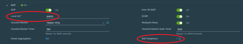
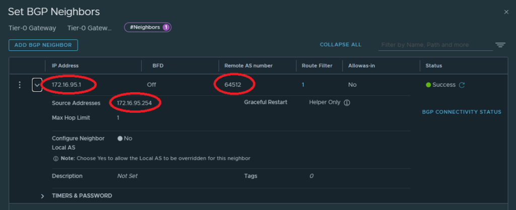
When setting the BGP Neighbors, the IP Address is the IP Address for the BGP neighbor, which is most likely the same IP address that would be used if a Static Route were used. In my lab, this would be the interface I would egress my traffic to, 172.16.95.1. The Remote AS number is the AS I assigned in my pfSense BGP configuration. Finally, I just needed to provide a Source Address, which in this case is the assigned Interface of the Tier-0 Gateway, 172.16.95.254.
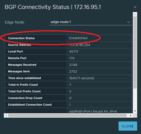
To check the BGP Connectivity, click the link and verify the Connection Status is Established.
Connectivity Between Tier-0 and Tier-1 Gateways
This may have been configured, already, during previous configurations, but I will include here for completeness and since this is step 6 of the suggested order of configuration.
Once the Tier-0 and Tier-1 Gateways are configured, edit the Tier-1 Gateway and choose a Tier-0 Gateway under the Linked Tier-0 Gateway.
Verify Network Topology
Networking > Connectivity > Network Topology
Yes, there is still one step left, to configure route advertisement and redistribution, but now is a good time to verify the Network Topology. Now would be a good time to verify and correct, if needed.
As of right now, there should be Segments, which may be connected to Tier-0 or Tier-1 Gateways, most likely a Tier-1, though. Then there should be a Tier-0 Gateway configured as well.
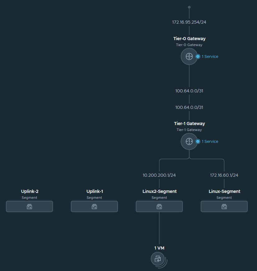
We can verify the IP Addresses configured and even drill down into the Fabric View by double-clicking on a network object.
Route Advertisement and Redistribution
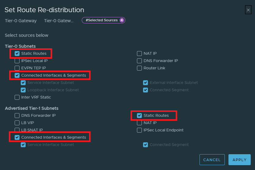
Edit the Tier-0 Gateway and expand Route Re-Distribution heading. Click on the link next to Route Re-Distribution.

On the Set Route Re-distribution window, provide a name and set the Route Re-distribution.
Choosing the route sources to re-distribute.
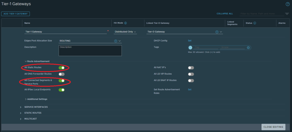
Edit the Tier-1 Gateway and expand Route Advertisement sub-heading. I only selected All Static Routes and All Connected Segments & Service Ports.
Conclusion
I would be lying if I said this was easy. While I have only touched the surface of getting to understand NSX, I am happy that I have this level of working knowledge at this point. I am hoping my knowledge will continue to expand and NSX will be more natural for me to install, configure, and manage.
Leave a Reply