Overview
This is my baseline build guide for VMware Avi Load Balancer 31.2.
All future Avi posts assume this deployment model.
This document captures the exact build sequence, non-default decisions, and failure points encountered during cluster formation.
Deployment Model Assumed
- vCenter-integrated Cloud
- Three-node Controller Cluster
- Enterprise License
- Static IP management
- Dedicated SE management network
RTFM
Sticky Points
- Controller clustering must use management IP addresses (not FQDN).
- Controller management interface is configured as either IPv4 or IPv6 (not dual-stack).
- All Controller nodes in a cluster must have identical CPU, memory, and storage configuration.
- For vCenter-integrated clouds, Service Engines (SE) are automatically deployed by the Controller.
- New installations of Avi Controller in VCF 5.2 and later environments must be performed through VCF Lifecycle Management.
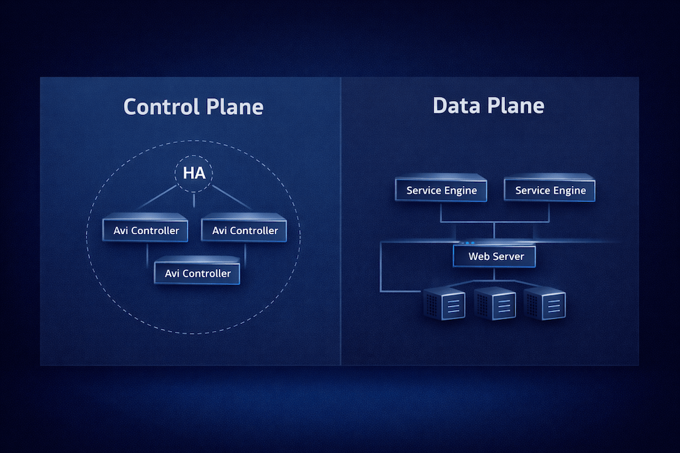
VMware Avi Load Balancer Architecture
VMware Avi Load Balancer is an Application Delivery Controller (ADC) that is configured primarily through a REST application programming interface (API) and the web UI. It comprises a Control Plane and a Data Plane.
Avi Controller (Control Plane)
Manages policies, infrastructure discovery, and the lifecycle of Service Engines (SE). It connects to vCenter through APIs and can be deployed as a single instance or a high-availability (HA) cluster.
Avi Service Engines (Data Plane)
Service Engines (SE) handle application traffic, provide load balancing, and collect end-to-end metrics.
In VMware environments, Avi Controllers and Service Engines run as virtual machines (VMs) managed by vCenter. The Controller can integrate with vCenter, and optionally NSX, through their respective APIs for automated infrastructure discovery, configuration and data plane lifecycle management.
The deployment involves two stages:
- Installation of the VMware Avi Controller.
- Cloud Configuration, which has the following four options:
- VMware vCenter / vSphere ESX cloud
- NSX Cloud – Overlay segments
- NSX Cloud – VLAN-backed segments
- No Orchestrator cloud
Deployment
Ensure management IP addresses, DNS, NTP, and vCenter service account credentials are confirmed before beginning the deployment.
Deploy the OVA
Deploy the Avi Controller OVA from a Content Library.

Provide a virtual machine name and select a location for the virtual machine.

Select a compute resource. Leave ‘Automatically power on’ unchecked so you can resize the VM before first boot (recommended, especially for clusters).

Review the details of the template.

Select the appropriate storage, disk format, and optionally the storage policy.

Select the network to be used for managing the controller nodes.

On the Customize template screen, you have the option to configure either an IPv4 address or an IPv6 address on the Management Interface. Unfortunately, this appliance is not currently dual-stack compatible.
The only values that need to be filled in are:
- Default password
- Either Enable IPv4
- Management Interface IP Address
- Management Interface Subnet Mask
- Default Gateway
- Or Enable IPv6
- Management Interface IPv6 Address
- Management Interface Subnet Mask (IPv6 prefix length)
- Default v6 Gateway

Since I configured IPv4 above, I am setting Enable IPv6 to False.


Finally, review the Ready to complete details.

If you are deploying a three-node Controller cluster, repeat the steps for the other two Controller cluster nodes.
To save time, if you are deploying a cluster, resize the node as necessary following the next section and power up the node. The primary node needs 10 to 20 minutes to fully configure. It is also the node that initially is configured to stand up the cluster.
Resize the Controller
Edit the virtual machine hardware in vCenter according to the recommended sizing using the table below. Optionally, I included the link with more details on how to appropriately size. This will ensure optimal performance in the environment. Note that if deploying a three node cluster, all nodes must be configured with identical CPU, memory, and storage configurations to be in a cluster.
Avi Load Balancer Controller Sizing
The size of the deployed appliance is small by default.
| Size | CPU | Memory | Storage |
|---|---|---|---|
| Small | 6 | 32 GB | 512 GB |
| Large | 16 | 48 GB | 1.4 TB |
| X-Large | 16 | 64 GB | 1.75 TB |

Power On the Controller
Power on the virtual machines and give them 10 to 20 minutes to fully configure.
Setting up the Initial Avi Controller
By now, the Avi Controllers should be online. Navigate to the URL using the fully-qualified-domain-name (FQDN) of the designated primary node.

The Deployment Password is the password that was configured during the OVA deployment labeled Default password.
On the Welcome Admin page:
- Enter a Passphrase that is used to encrypt sensitive fields for export and periodic backup
- Provide DNS servers (comma separated) — be sure to provide DNS servers with the same IP version that was configured. IPv4 or IPv6, not both.
- Provide the DNS search domain
- Choose whether to join the VMware Customer Experience Improvement Program (CEIP)

Configure the Email/SMTP settings if you have them available, otherwise, this can be configured later.

During initial setup, I configured the Multi-Tenant with Share IP route domain across tenants, the Service Engines are managed within the Provider (Shared Across Tenants), and with No Access. This model reflects a centralized enterprise Application Delivery Controller (ADC) design where infrastructure components (Service Engine Groups, IPAM, DNS profiles, and shared policies) are controlled by the platform team, while logical tenant separation can be introduced later without requiring separate routing domains. It simplifies networking, avoids route duplication, and aligns with most corporate data center deployments.

To configure the Cloud now, select the Setup Cloud After checkbox.

Configuring the Cloud Connector
For simplicity, I am going to configure a VMware vCenter/vSphere ESX cloud. There are various other Types that can be configured.

Configuring the Cloud Connector
Use the Get Started wizard for this. On the Infrastructure tab, choose the Get Started menu item on the left.

Select Get Started under the vCenter Cloud Quick Start Wizard tile.
Review the Prerequisites and select Completed Prerequisites.

Since I am only going to configure a single cloud, so I am going to use the Default Cloud.

Provide the details of the vCenter server and the credentials. I chose to use a local account on vCenter for this.

Choose a Datacenter and Content Library.

Configure the Service Engine Management Networking. I chose the port group and then configured the network details. I am not using DHCP on this network, so I needed to also configure a pool of addresses. The VMware Avi Load Balancer has a built-in IP Address Management (IPAM) that can be used.

Synchronization will take place. During this time, the Content Library will be populated with the Service Engine OVA, about 4.0 GB.

You can check if the service account logged in to vCenter by checking the top of the vCenter tree on the left > Monitor > Tasks and Events: Sessions

Once the synchronization is complete, the Review and Confirm screen will display.

IP Address Management (IPAM) — I do not have an IPAM solution, but I do plan on having automatic VIP allocated. For this, I will still use the Service Engine (SE) network, just a further range of IP addresses.

The next screen allows you to configure other additional settings. In the Additional Configuration Items section, I will add additional IPv6 networks to the subnets we made during the wizard.

Since this completes the vCenter Cloud Quick Start Wizard, it’s time to Finish up here and refine a few additional configuration items.
Additional Configuration Items
Service Engine Pool IPs
I use IPv6 in my lab, so I want to add a pool of IPv6 addresses to the Service Engine (SE) management subnet. Note that Service Engines can be dual-stacked while the Controller or Controller Cluster can only be single-stack.
Infrastructure > Cloud Resources: Networks > VLAN166 – Service Engines and select edit.
Since I plan on assigning static IP addresses, I uncheck the option to Enable DHCP and Enable IPv6 Auto Configuration.

Select Add to add additional networks. Configure the Subnet Prefix and add an IP Address Range. I want to control what each portion of the subnet is used for so I decided to uncheck the Use Static IP Address for VIPs and SE option. This is not necessary, I could leave this option checked and let the Avi IPAM handle it, but I wanted to document this split as an option.
I will match the range of my IPv4 addresses for each use based on the last number, but I know with IPv6, there will actually be 154 usable IP addresses compared to the 100 usable in IPv4. The IPv6 subnet provides more usable addresses than the equivalent IPv4 range.
- 100 – 199 for Service Engine (SE) Management
- 200 – 254 for Virtual IP (VIP)

Now we can verify the Network Settings for our designated Service Engine (SE) Management subnet.

Configure NTP
Time is a critical component for an enterprise system to function correctly and also a key component in properly securing systems. By default, the Avi Controller will have NTP Servers configured, but they may not be the desired sources or fit with the organizational policy.

Administration > System Settings > Edit > DNS/NTP
Modify the entries as needed. In my case, I run two Rocky Linux servers that provide NTP services, so I am using those for my infrastructure time.

Licensing
Without a license configured, we won’t be able to do much. Head over to Administration > Licensing and select the gear.

I am going to select the Enterprise Tier and then save the dialog.

In my case, I am evaluating VMware Avi Load Balancer, so I am going to be using the Eval license listed in the available Licenses. There is nothing to select. As long as there is a license that has not expired, the Service Engines will deploy. If you have a License Key or a License File, add them and verify they show in the list of available Licenses.

Service Engine Group
By default, all Service Engines (SE) are deployed into the Default-Group. For quick testing, that may work, but it is better to configure prescriptive and deterministic groups.
Infrastructure > Service Engine Group > Create
I am going to create two groups, one will be for L4 Pass-through while the other will be for L7 Break-and-Inspect. One thing that I do not see configurable in these menus is anti-affinity rules. According to the documentation, if the SE group is set to Active/Active, the controller will deploy to separate ESXi hosts.
So it may still be necessary to create anti-affinity rules after these deploy. Just know that SEs are ephemeral, meaning they will likely be torn down and rebuilt with major configuration changes. Also, if the last or only virtual service gets removed or disabled, it is also likely the SEs will be destroyed.
1. The “Standard-L4” Group
Use Case: L4 Passthrough, DNS, and basic load balancing.
- General > Name: Standard-L4
- Placement > High Availability Mode: N+M (buffer)
- Placement > Virtual Service Placement Across Service Engines: Compact (Pack multiple small services onto the same SE to save resources).
- Resource > Service Engine Folder: AviSeFolder
- Resource > Service Engine Name Prefix: Avi
- Resource > vCPU per Service Engine: 1
- Resource > Memory per Service Engine: 2 GB
2. The “Secure-L7” Group
Use Case: SSL Termination, WAF, and “Break-and-Inspect.”
- General > Name: Secure-L7
- Placement > High Availability Mode: Active/Active
- Placement > Virtual Service Placement Across Service Engines: Distributed (Spread Virtual Services across SEs to ensure no single SE becomes a bottleneck).
- Resource > Service Engine Folder: AviSeFolder
- Resource > Service Engine Name Prefix: Avi
- Resource > vCPU per Service Engine: 2
- Resource > Memory per Service Engine: 4 GB
Configuring the Cluster
Now we can configure the Avi Load Balancer Controller Cluster.
Clustering Note: Controller clustering must be performed using management IP addresses. Attempting to use FQDN during cluster formation can result in failed service initialization and persistent HTTP 503 responses across all nodes. If this occurs in a fresh deployment, redeployment is the recommended recovery path.
Before forming the cluster, verify:
- All three Controllers are individually reachable via HTTPS.
- DNS resolution is functional for UI access.
- NTP is configured and time is synchronized across nodes.
- Node sizing is identical.
- Management IPv4 addresses are confirmed and reachable between nodes.
Navigate to Administration > Controller: Nodes and click Edit.
Add a Name, Controller Cluster IPv4 or IPv6 address and add the Cluster Nodes. When adding the Cluster Nodes, even though the UI mentions FQDN, only use the IPv4 or IPv6 address. For the hostname, it is recommended to use the fully-qualified-domain-name there.

According to the documentation:
After these steps, the incumbent Controller becomes the leader of the cluster and invites the other Controllers to the cluster as follower members. Avi Load Balancer then performs a warm reboot of the cluster. This process can take 2-3 minutes. The configuration of the leader Avi Load Balancer Controller node is synchronized to the new follower nodes when the cluster comes online following the reboot.
After a few minutes, I received this pop-up.

The primary node started to show an Inactive state.

This webpage may also show while the Controller is rebooting.

If this screen is up for more than 30 minutes, however, it’s likely the cluster bring-up failed.
Refresh the browser and log back in if asked. When I logged back in, one of my nodes was a little slow to start up.

After a few more minutes, I just refreshed the browser again and this time, all the nodes showed up as Active.

Troubleshooting – Cluster Bring-up Failure
The following scenario was observed during initial lab deployment and is preserved here to prevent repeat failure.
Symptom
- Web UI unavailable after clustering
- HTTP 503 on all nodes
- UI stuck in reboot state > 30 minutes
Quick Verification
SSH to one node:
systemctl list-units --type=service --failedIf multiple redis-server@xxxx services are failed, cluster bootstrap did not complete.
systemctl list-units --type=service --failed
  UNIT                      LOAD   ACTIVE SUB    DESCRIPTION
● [email protected]     loaded failed failed DB Cache Redis Server 5055
● motd-news.service         loaded failed failed Message of the Day
● [email protected] loaded failed failed Redis Server 5001
● [email protected] loaded failed failed Redis Server 5035
● [email protected] loaded failed failed Redis Server 5036
● [email protected] loaded failed failed Redis Server 5037
● [email protected] loaded failed failed Redis Server 5038
● [email protected] loaded failed failed Redis Server 5058

Legend: LOAD   → Reflects whether the unit definition was properly loaded.
        ACTIVE → The high-level unit activation state, i.e. generalization of SUB.
        SUB    → The low-level unit activation state, values depend on unit type.

8 loaded units listed.
Evidence
Inspect /etc/hosts:
- Presence of
nodeX.controller.local - Loopback (127.x.x.x) bindings
- Inconsistent cluster metadata
cat /etc/hosts
127.0.0.1       localhost

127.0.0.1    avic-v164-104
#used by zk_servers: node1.controller.local {127.0.0.1, avic-v164-104.lab.aaronrombaut.com}
127.0.0.1  node1.controller.local
#used by zk_servers: node3.controller.local {127.0.0.7, avic-v164-105.lab.aaronrombaut.com}
127.0.0.7  node3.controller.local
#used by zk_servers: node2.controller.local {127.0.0.8, avic-v164-106.lab.aaronrombaut.com}
127.0.0.8  node2.controller.local
Root Cause (Lab Scenario)
Cluster was initiated using FQDN instead of management IP addresses.
Internal ZooKeeper (ZK) cluster metadata was generated using hostname mappings, resulting in inconsistent service discovery and Redis startup failure.
Resolution
For fresh deployments:
- Destroy Controller nodes.
- Redeploy clean.
- Form cluster using IPv4 management addresses only.
- Do not mix IP versions.
- Do not use FQDN during cluster formation.
Attempting to repair corrupted cluster state is not recommended in non-production environments.
Conclusion
This baseline deployment now serves as the reference model for all subsequent Avi Load Balancer configuration posts. Future topics assume a three-node Controller cluster, vCenter-integrated cloud, defined Service Engine groups, and functional IPAM configuration.
Leave a Reply